A typical single-driveway residential install takes one full day for a competent DIYer or half a day for a two-person crew, while commercial and HOA installations require multi-day work with inspection sign-off. The right electric gate opener installation is a compliance and risk-engineering project first, then a mechanical and wiring project.
The familiar scenario is a gate that works perfectly by hand, but leaves residents carrying clickers, managers issuing shared codes, and installers returning after a sensor misalignment or intermittent splice. A modern gate operator can add convenience, but only when the gate structure, power system, entrapment protection, and access controls are commissioned as one system.
For property managers, HOA boards, security installers, and residents, the practical question isn't just whether an opener can move the gate. It's whether the completed system can operate safely, remain serviceable, and support modern access credentials without forcing a full gate replacement.
Table of Contents
- Before You Start, Treat It as a Safety Project
- Tools, Materials, and Safety Gear You Need
- Site Assessment and Operator Mounting
- Wiring, Power, and Battery or Solar Setup
- Entrapment Protection and Sensor Placement
- Programming, Force Testing, and Commissioning
- Adding Cellular App Access with a Nimbio Retrofit
Before You Start, Treat It as a Safety Project
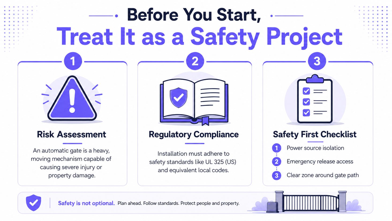
An automatic gate is a heavy moving mechanism capable of crushing a child, a pet, or a vehicle. In the United States, the project must account for UL 325, while other jurisdictions apply equivalent machinery-safety requirements. The standard became central to modern practice after documented entrapment deaths and injuries in the 1990s helped drive the March 2000 edition of UL 325 and its gate-related safety requirements, as explained in this UL gate-operator safety document.
Before any tool leaves the truck, the installer should complete the desk work:
- Verify the operator listing: Confirm that the gate operator is UL 325 listed and suitable for the gate's weight, length, travel direction, and duty classification.
- Check local approval: Pull the electrical or building permit when the jurisdiction requires one, and determine whether the authority having jurisdiction expects documented commissioning.
- Locate utilities: Call 811 before digging posts, installing a pad, or trenching for power. A missed underground service can turn a routine installation into a dangerous excavation.
- Review the hinge arc or slide path: Decide where the operator head will sit in relation to the moving gate, fence line, pedestrian route, and public sidewalk.
- Confirm the power route: Survey the distance to the 120/240 V service before the equipment is ordered. Skipping this step because nobody wanted to run a new circuit is a reliable way to create callbacks.
Gate construction also matters. A flexible aluminum frame, a sagging wood gate, and a rigid steel gate impose different loads on brackets and operator arms. If the existing fencing needs repair before automation, property owners can use a local resource to compare fencing estimates Texas before the opener is mounted.
The scope changes quickly by property type. A single driveway may fit into a day for a competent DIYer or half a day for a two-person crew, while commercial and HOA projects commonly span multiple days and include inspection sign-off.
Tools, Materials, and Safety Gear You Need
A clean installation depends on staging the right parts before drilling or wiring. One missing weatherproof box or mounting fastener can leave an operator exposed and send the installer back to the supply house.
Stage materials by function
Mechanical materials must suit the gate, not just fit inside the opener kit. Prepare the operator, mounting brackets, bolts, stainless steel washers, and fasteners matched to wood, steel, or aluminum. Post brackets may require concrete mix or no-dig backfill. Terminate every exterior splice inside a weatherproof junction box.
Control wiring needs a separate route from line voltage. Use low-voltage direct-burial cable, commonly 12-2 or 14-2 for accessories, and keep it separated from power conductors. Gel-filled splices belong in damp or buried runs. Ordinary wire nuts and unsealed connections allow moisture to enter and often cause intermittent faults later.
For the power circuit, follow the conductor gauge listed in the operator manual's distance chart. Runs exposed to physical damage generally use THWN conductors inside conduit. Provide the required dedicated GFCI protection in accordance with local electrical rules.
Bring tools that prevent rework
A practical loadout includes:
- Drilling equipment: A rotary hammer and masonry bits for concrete or masonry posts.
- Fastening tools: An impact driver for installation and a torque wrench for final arm and bracket tightening.
- Electrical test gear: A multimeter, fish tape, labels, and a noncontact voltage tester.
- Alignment tools: A 4-foot level and laser plumb for brackets, racks, posts, and operator pads.
- Finishing equipment: A cordless grinder for removing burrs and smoothing rough metal edges.
Protect workers and the public
Wear ANSI Z87.1 safety glasses, cut-resistant gloves, and hearing protection while drilling or grinding. Use a hi-vis vest when the gate faces traffic or the work zone reaches a public route. Keep loose clothing, hands, and bystanders away from moving equipment during testing.
Practical rule: Gel-filled splices prevent a common delayed electrical fault in damp runs. An opener can pass handover testing, then develop intermittent problems after moisture reaches an unsealed connection.
Site Assessment and Operator Mounting
The operator can only be as reliable as the gate it moves. Before drilling, walk the property line and operate the gate manually through its entire travel. The gate should swing or slide freely, without binding, scraping, excessive sag, or a hard spot that the motor will later be forced to overcome.
Four checks determine whether the mounting location is usable:
- Travel quality: Confirm that hinges, rollers, tracks, stops, and wheels support smooth movement.
- Arm geometry: Check that the operator arm clears the hinge arc through the full cycle.
- Mounting strength: Make sure the post, column, or pad can absorb repeated shock loads without flexing.
- Reach protection: Place the operator head where a person can't reach the moving arm during operation.
For a pull-to-open swing gate, the post bracket should leave the arm fully retracted when the gate is closed. At full open, maintain at least 2 inches of clearance from a column or fence post. The exact bracket position still depends on the operator manual, gate dimensions, and hinge geometry.
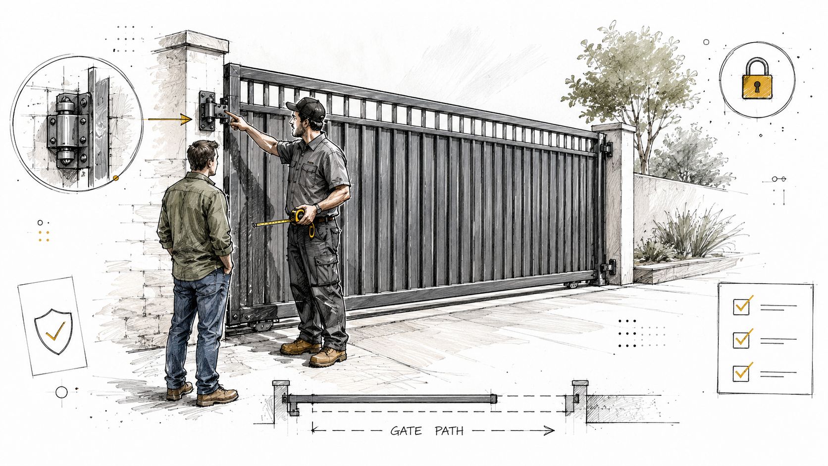
Slide gates need a different inspection. The rack must be straight, level, and parallel to the operator pinion throughout travel. The operator foundation should extend below frost depth in cold climates, because seasonal movement can shift the drive relationship and create repeated stalls.
Mounting hardware deserves a controlled final pass. Torque the bolts to the manufacturer's specification, commonly 35 to 50 ft-lbs for lag or carriage bolts where the manual calls for that range. Stainless steel washers are preferable to over-tightening into soft wood, which can crush the mounting surface without producing a stable connection.
The recurring callback is a post bracket that pulls a few millimeters under load. The gate may move during a hand test, then stall or reverse on every powered cycle. A rigid backing plate or structural reinforcement solves that problem more reliably than increasing motor force.
Wiring, Power, and Battery or Solar Setup
Power and control wiring should be planned before the operator is mounted. Run the low-voltage cable from the transformer or power source to the operator while keeping Class 2 control wiring separated from 120/240 VAC mains. That separation follows NEC 725 principles and helps prevent induced noise on the control bus.
At the operator terminal block, confirm polarity before energizing:
- Red: Positive
- Black: Negative
- White: Common
- Green or bare: Chassis ground
Reversed polarity can lock out many control boards. A dedicated circuit should be sized according to the manual and local electrical requirements, with the plan here calling for 15 A minimum for single-family installations. Where line voltage is exposed, THWN in Schedule 40 PVC provides a more defensible physical installation than unprotected conductors.
Measure voltage at both ends under load. The design target is less than 5% voltage drop, with a second parallel conductor or larger wire gauge considered for runs over 100 ft. Every conductor should be labeled at both ends, and terminal screws should be torqued to the manufacturer's specification.
Battery and solar systems require more than attaching a panel. A sealed AGM or lithium battery belongs inside the operator housing when the manual permits it, wired through the board's BAT port with the supplied fuse in line. The charger's float voltage must match the battery chemistry.
For solar, calculate daily amp-hour demand from the gate's duty cycle, multiply that load by 1.5 for worst-case winter sun, and select a panel with at least a 20W buffer for recharge capacity. One published battery-opener manual specifies a 12V DC operating system and says a solar configuration requires an additional 12V battery, producing two 12V batteries for solar operation, as shown in this battery and solar installation manual.
| Power Option | Typical Run Length | Backup Runtime | Relative Cost |
|---|---|---|---|
| Hardwired AC | Short to long, based on service location | Battery-dependent | Lower equipment cost, trenching may add labor |
| Battery backup | Local to operator housing | Depends on battery capacity and gate use | Moderate |
| Solar with battery | Useful where utility power is distant | Depends on sun exposure and battery capacity | Higher equipment cost, lower dependence on grid wiring |
For unusual mechanical systems, installers may also review gear motors for hydraulics to understand how motor and gearbox choices affect driven equipment. For low-voltage routing and operator connections, consult Nimbio installation wiring advice.
Entrapment Protection and Sensor Placement
A gate that opens and closes is not necessarily a safe gate. UL 325 guidance generally calls for at least two independent entrapment-protection means in each direction of travel, and external sensors must be monitored by the operator. The operator should detect a failed sensor and refuse to close rather than operating without protection, as described in this UL 325 entrapment-protection guidance.
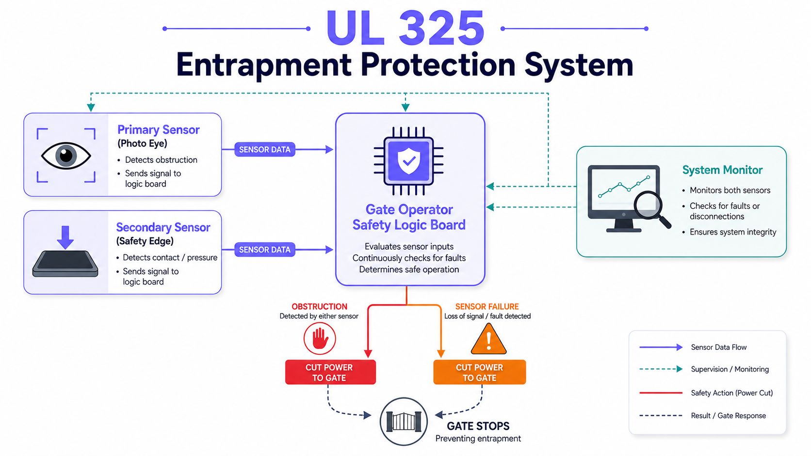
The primary device is usually a monitored photoeye. A common placement is 6 in. above grade across the gate path, with a clear line of sight and rigid brackets that won't shift when a vehicle brushes the post. Wire the photoeyes as a normally closed loop in series when the manufacturer's diagram calls for that arrangement, so a broken conductor or open circuit stops movement.
The secondary device depends on the gate design:
- Swing gate: A monitored contact edge can run along the leading edge, where it compresses before a rigid gate member reaches a post or vehicle.
- Slide gate: A safety edge can protect the bottom rail or leading edge, depending on the entrapment zones identified during the site survey.
- Redundant sensing: A second monitored through-beam or wireless edge can provide independent protection where the geometry creates additional hazards.
Sensor placement should account for the environment. Sprinklers, leaves, mud, and direct sun can cause nuisance trips or obscure a beam. Rigid mounts and hooded brackets help, but they don't replace a clear line of sight and a documented test.
After installation, perform the manufacturer's obstruction test and confirm that the operator board recognizes each monitored device. If a photoeye is misaligned, use a structured process to fix gate photo eye alignment, then repeat the obstruction test. The final as-built diagram should identify both entrapment devices, their wiring paths, and the protected zones.
UL 325 safety engineering has produced a meaningful historical benchmark. UL Standards & Engagement reports that the standard has been associated with more than a 50% decrease in incidents, fatalities, and entrapments as a share of garage-door injuries when compared through CPSRMS data, as documented in this UL 325 impact report. The lesson for gate installers is direct: partial compliance can leave a functioning system unsafe.
Programming, Force Testing, and Commissioning
Commissioning shouldn't mean pressing learn buttons until the gate moves. It should establish known travel limits, safe force behavior, working emergency release, and a documented access configuration.
Teach travel before adding credentials
Start with a factory reset so old limits don't influence the new installation. Decouple the operator and hand-cycle the gate to confirm that the hinges, rollers, stops, and track are free before the board learns travel.
Re-engage the operator and run one complete cycle under observation. Adjust open and close limits in small increments until the gate seals or stops correctly without slamming. A limit adjustment can't correct a bent track or a bracket that shifts under load.
Set force conservatively
Set motor force to the lowest value that reliably moves the gate under load. Increasing force isn't a safety upgrade. It can increase the consequences of an obstruction and create a liability problem.
The UK HSE advises installers to use the correct test equipment to measure opening and closing forces. If that equipment isn't available, the gate shouldn't be installed because compliance can't be verified. The guidance recommends measurement to BS EN 12445, along with force limitation and obstacle detection, as explained in this HSE powered-gate safety bulletin.
Place a 2×4 flat in the travel path and conduct reversal tests in each direction. The gate should stop and reverse within the manufacturer's specified window, commonly under 2 seconds where the operator documentation uses that criterion.
Verify release and record the system
The manual release key should turn smoothly, and the gate should be pushable by hand when the drive is disengaged. Program remotes, keypads, and any cellular controller only after force testing passes.
The owner's maintenance file should include:
- Final open and close limits
- Force settings
- Firmware version
- Commissioning date
- Access-device labels
- Obstruction-test results
- Emergency-release confirmation
Sign and date the UL 325 compliance sticker on the operator. A clear record helps an HOA manager, service technician, or inspector understand what was tested and what settings were accepted.
Adding Cellular App Access with a Nimbio Retrofit
Replacing a working operator just to add smartphone access is often unnecessary. A cellular controller can use the existing operator's trigger input, allowing a property manager or homeowner to modernize access while preserving the gate, motor, safety devices, and hardwired controls already in service.
The retrofit starts with compatibility, not the app. Confirm whether the operator supplies 12 VDC or 24 VAC, identify the correct accessory terminals, and verify that the controller's relay output matches the gate board's open command. A mismatch between power requirements is an avoidable ordering error.
Inspect the existing operator first
The gate should already pass the mechanical and safety checks described above. A cellular module won't repair a failing hinge, weak post bracket, damaged rack, misaligned photoeye, or operator board that reverses under normal load.
A practical pre-retrofit inspection covers:
- Operator condition: Confirm normal open and close cycles without unexplained stalls.
- Safety inputs: Verify that monitored photoeyes and edges are recognized by the board.
- Power availability: Identify a weather-protected source near the operator.
- Control terminals: Locate the dry-contact or accessory input used for a request-to-exit, keypad, remote receiver, or push button.
- Backup access: Confirm that a hardwired keypad or remote can remain in parallel.
The controller should be mounted in a weather-protected location near the operator board, with enough room for service access and cable bend radius. Power it from the operator's approved supply or a dedicated power source, then land the relay terminals on the gate's open command and accessory input according to the operator and controller wiring diagrams.
Provision the cellular controller
After the wiring is complete, pair the device with its cellular network and claim it in the mobile application. The installer should test the relay locally, then confirm that an authorized phone can open the gate from the intended coverage area.
A cellular connection is useful where Wi-Fi drops, changes ownership, or doesn't reach the operator cabinet. It also supports remote visitor management and access credentials without requiring the property to distribute additional clickers or maintain a shared keypad code.
A system such as Nimbio can be used as a hardware-agnostic retrofit for compatible electronic gate operators. It provides cellular app control, digital key management, scheduled credentials, and entry-log visibility while leaving existing remotes and keypads in parallel. The installation path to retrofit a cellular gate opener should still follow the operator manufacturer's wiring requirements and local electrical rules.
Configure access for real operations
For a single residence, the administrator might issue a digital key to household members and a time-limited credential to a contractor. For an HOA or multifamily site, the manager can assign credentials to residents, vendors, and service teams, then revoke or reschedule them without collecting physical devices.
A sound configuration includes:
- Resident credentials: Create individual access rather than one shared code.
- Vendor schedules: Limit landscaping, delivery, and maintenance access to approved windows.
- Visitor handling: Use remote approval when the property needs a resident or manager to verify entry.
- Log review: Confirm that access events appear with the expected user or credential.
- Fallback controls: Keep a hardwired keypad or remote in parallel so residents aren't locked out solely because cellular service is temporarily unavailable.
The app should not become the primary credential immediately after wiring. Run a one-week soak test with normal users, scheduled credentials, the fallback control, and entry-log review. Correct any relay timing, access assignment, or operator behavior issue before removing legacy access methods.
Match the project scope to the gate
Time depends on gate type and site complexity. A half-day DIY retrofit may suit a single swing driveway when the operator is accessible and the wiring is straightforward. A dual-leaf or sliding installation can require a full day, while commercial or HOA operators with inspection sign-off can require two to three days.
Cost should be evaluated by scope rather than by the controller alone. A budget DIY retrofit generally assumes an accessible operator, existing conduit or short wiring paths, and an owner supplying labor. A mid-range professional installation adds site testing, weatherproof terminations, configuration, and commissioning. A turnkey commercial build can include new conduit, structural repairs, additional safety devices, inspection documentation, credential setup, and ongoing service.
The following matrix helps determine who should perform the work:
| Project condition | In-house work may fit | Contracted installation is safer |
|---|---|---|
| Gate structure | Light residential gate with sound hinges and posts | Heavy gate, masonry pillars, sagging frame, or damaged track |
| Access volume | Low-cycle private driveway | High-cycle commercial, HOA, or multifamily entrance |
| Electrical scope | Existing approved low-voltage route and accessible power | New line-voltage circuit, trenching, or complex conduit |
| Site exposure | Private property with no public interface | Public right-of-way, sidewalk, or emergency-access route |
| Inspection | No required commissioning sign-off | Jurisdiction requires UL 325 documentation or inspection |
| Construction | Surface mounting with shallow work | Footings deeper than 24 inches, finished-driveway trenching, or concrete demolition |
A licensed installer should handle masonry pillars, footings deeper than 24 inches, public right-of-way exposure, missing low-voltage conduit, required UL 325 commissioning sign-off, and any trench across a finished driveway. The same applies when the gate's weight, cycle volume, or liability exposure exceeds the team's practical experience.
For property managers and HOA boards, the retrofit decision is ultimately about control and accountability. Cellular access eliminates dependence on Wi-Fi drops, preserves existing gate hardware, and gives administrators a way to manage remote visitors and credentials without distributing untraceable shared codes. The operator still needs sound mechanical installation and safety validation, but the access layer can be modernized without replacing the entire gate system.
Nimbio provides cellular, smartphone-based access control that can retrofit compatible electronic gates while preserving existing remotes and keypads. Visit Nimbio to evaluate a gate-access retrofit with remote visitor management, digital credentials, and entry-log visibility.