A gate that opens slowly, stops halfway, or reverses for no obvious reason often gets blamed on the operator. In many cases, the motor is only exposing a problem that was already present in the gate, posts, foundation, wiring, or safety layout. Gate operator installation starts with site readiness, then moves through mechanical mounting, electrical work, entrapment protection, and documented commissioning.
Table of Contents
- What a Gate Operator Installation Actually Involves
- Site and Gate Readiness Before You Mount the Operator
- Mechanical Mounting for Sliding and Swing Operators
- Electrical Rough-In, Wiring, and Grounding
- Safety Devices and UL 325 Entrapment Protection
- Commissioning, Testing, and Final Adjustments
- Retrofit Tips and Adding Smart Access to an Existing Operator
What a Gate Operator Installation Actually Involves
A proper gate operator installation is a sequence of decisions, not a quick motor swap. The installer first checks whether the gate is structurally sound and moves freely. Next comes the choice between a sliding or swing arrangement, followed by operator sizing for the gate's physical load and expected operating demand. Power, control wiring, safety devices, access patterns, and commissioning all have to fit the same design.
The operator is the visible part of the system, but it isn't usually the source of the worst callbacks. A sliding gate with drag in the rollers can overload a correctly selected motor. A swing gate with loose hinges can create changing arm geometry. A shifting post can turn accurate measurements into a failure after the first weather cycle.

The decisions made before mounting
A field-ready sequence normally includes:
- Gate condition: The leaf or panel must move without binding, dragging, or sagging.
- Operator selection: Residential, commercial, light-duty, and higher-use equipment have different limits. The manufacturer's capacity and duty information controls the choice.
- Foundation and geometry: The pad, posts, hinges, track, rack, arm, and stops must provide stable alignment through the full movement.
- Electrical planning: Power and low-voltage controls need protected routes, suitable conductors, and a layout that can be serviced later.
- Safety design: Entrapment devices must protect each applicable area and remain active during operation.
- Commissioning: Limits, force response, reversing behavior, access controls, and emergency release must be checked under realistic conditions.
The governing framework is broader than a mounting diagram. UL 325 guidance for gate operators points installers toward independent entrapment protection, ASTM F2200, local electrical codes, and qualified installation. Local permitting and inspection requirements vary, so the installer must confirm them before work begins.
A clean installation is roughly 20% mechanical work and 80% preparation, planning, and safety verification as a practical rule of thumb. That ratio isn't a measured industry statistic. It reflects where experienced installers spend their attention, because mounting a motor is straightforward when the site has already been made ready.
Site and Gate Readiness Before You Mount the Operator
A gate can look serviceable and still be unsuitable for automation. If the panel binds halfway, a post shifts under load, or the slab leaves no usable route for conduit, mounting the motor only hides the defect until commissioning. Treat the site as a readiness check first, then bring the operator to a prepared structure.
Start with the gate itself. Push, pull, lift, and measure it through the complete opening cycle before uncrating equipment. A sliding gate should roll consistently on a straight track, with sound rollers, firm end stops, and enough room for the operator and rack. A swing gate should move freely in both directions, with hinges and stops that hold their position while the panel moves. Repair worn hardware before automation. The field guide from Anvil Field offers a practical inspection reference.
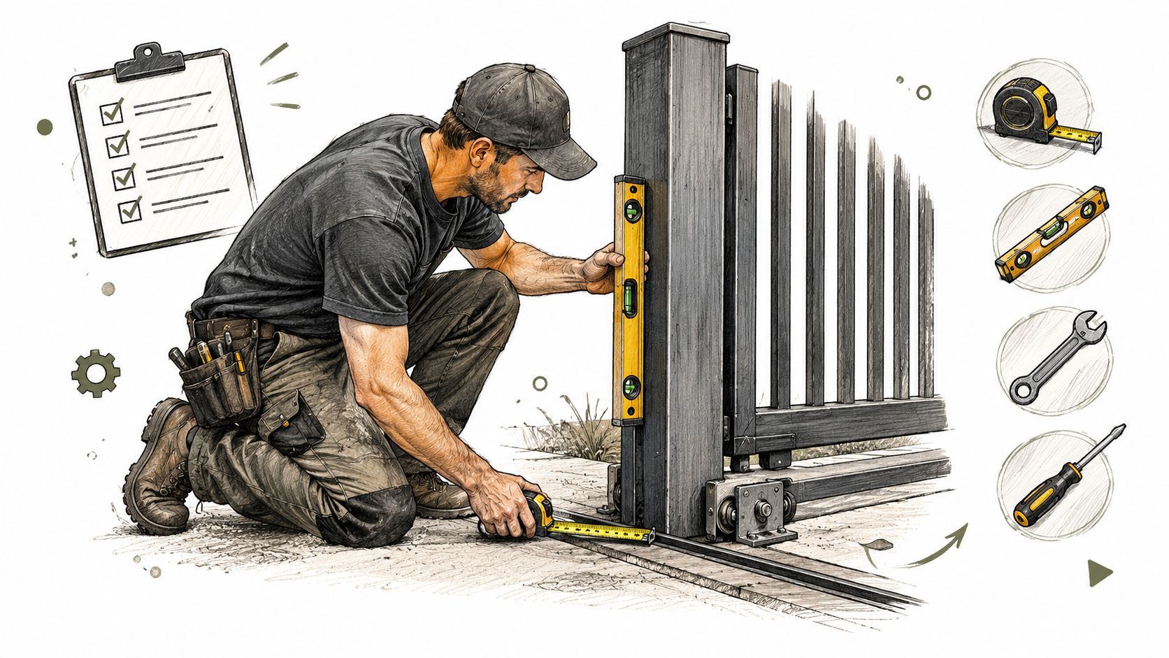
A pre-mount inspection
- Check movement by hand: Correct dragging, scraping, sudden resistance, and sag before applying power. The operator is not a repair tool.
- Inspect the support: Twisted frames, corroded hinges, loose rollers, and posts that move under pressure are structural defects. Adjustment will not correct them.
- Measure clearances: Record the gate-to-post gap, the space between dual leaves, the swing arc, and the operator envelope. The arm or rack needs a clear path without striking a column or creating a pinch point.
- Confirm the foundation: Provide a level, stable mounting surface with enough depth and reinforcement for the selected operator. Foundation dimensions must follow the equipment instructions and local conditions, including frost depth where applicable.
- Plan conduit paths: Mark entry points for power, controls, safety devices, and accessories before pouring concrete. Include bends, pull access, drainage, and a route that remains serviceable after the operator is installed.
For sliding systems, allow the concrete to cure for the period specified by the operator manufacturer before loading the pad. Position the gearmotor using the maker's stated adjustment clearance, then leave room for final rack and pinion alignment. Do not transfer a dimension from one model to another. The same discipline helps avoid costly hydraulic rework when a project includes hydraulic equipment, drainage concerns, or difficult foundation access.
Poor civil work is expensive to conceal and harder to correct after wiring. Verify the slab, gate path, and conduit route before mounting hardware.
Practical rule: If the gate does not move correctly by hand, stop the installation before applying power.
Mechanical Mounting for Sliding and Swing Operators
A gate that runs correctly by hand can still fail after the operator is mounted if the hardware is out of square. Small geometry errors become noise, wear, skipped movement, or missed limits. Treat the mounting stage as a mechanical alignment job: the operator stays fixed while the gate moves through its complete travel.
Sliding operator alignment
Begin with the manufacturer's anchor template and a level, reinforced pad. Set the operator parallel to the gate, then align the pinion with the rack across the entire opening. Fasten the rack continuously and keep its teeth engaged without forcing the operator toward the gate.
Leave adjustment available until the alignment has been tested. Move the gate manually from fully closed to fully open, checking for tight spots before final tightening. Excessive rack-to-pinion pressure creates noise and premature wear. Excessive clearance permits skipping and inconsistent travel. The sliding operator installation manual warns that the plate must be aligned, bolt threads must remain fully above the surface, and the rack must be secured along its length before the opening limit fin is set.
The anchor system must suit the concrete and the operator's mounting detail. Wedge anchors may work in suitable concrete, while another installation may require adhesive anchors or a specified manufacturer system. Substituting hardware without checking the equipment requirements can reduce embedment and pullout resistance, and may create a warranty dispute.
Swing operator geometry
Swing operators require a different mechanical check. Confirm whether the arm is configured for pull-to-open or push-to-open, then mount the post bracket to a structural post. Decorative covers and weak cladding are not reliable mounting points. Check the full hinge arc, including the final movement into the closed stop, so the arm does not bind or contact the post.
Keep the operator on the secure side of the gate rather than the public side. Insufficient clearance places extra stress on the operator and can create a physical hazard. Anvil Field's swing gate installation guide also stresses following the manufacturer's anchoring detail and keeping the manual release accessible during an outage.
Complete one full hand cycle before tightening every fastener. This catches an arm that contacts the post, a rack that tightens at one end, or an anchor location that blocks the intended stop. Start wiring only after the gate completes its travel without assistance.
Electrical Rough-In, Wiring, and Grounding
A gate can run during a quick demonstration and still fail under repeated cycles, voltage drop, or wet conditions. Treat the site as two wiring systems: the power circuit that starts and runs the operator, and the low-voltage circuits that carry commands and safety signals.
Start with the operator manual. It sets the supply voltage, conductor size, terminal layout, accessory limits, and acceptable wiring methods. Check motor starting demand, cable distance, outdoor exposure, conduit protection, disconnect location, and local electrical requirements before pulling cable. The circuit must suit the installed load, not just produce one successful test cycle.
Keep power and control circuits organized
Route power and low-voltage conductors separately unless the applicable code and manufacturer instructions allow another arrangement. Separation limits interference, reduces accidental contact, and makes future troubleshooting easier. A planned low voltage gate installation should also leave enough room to identify and service control wiring without disturbing line-voltage terminations.
Follow the model-specific diagram. Terminal positions vary between operators, even when the equipment appears similar. Identify every conductor at both ends, and mark spare cables before closing the enclosure. Where aluminum conductors are permitted, use the connector treatment specified by the equipment and electrical authority. Tighten terminals to the manufacturer's stated torque. Guesswork can damage a lug or leave a connection loose.
A rough-in check should cover:
- Power route: Verify the circuit, disconnect, conduit, weather protection, and service access.
- Low-voltage route: Protect cables serving photoeyes, edges, keypads, receivers, loop detectors, and other controls.
- Grounding and bonding: Bond the operator enclosure and equipment grounding conductors into the site grounding system as required.
- Labels and records: Mark conductors, document spare cables, and leave a wiring record inside the enclosure or project file.
Keep water out of every entry point. Use listed fittings, seal unused openings, form drip loops where appropriate, and prevent conduit from directing water into the cabinet. Check that the enclosure remains properly closed after wiring, with no pinched conductors or damaged gaskets.
The operator is part of an outdoor electrical system, not an isolated appliance. The UL safety overview for gate operators identifies fire, electric shock, casualty, and entrapment among the hazards addressed by its safety framework. Grounding, bonding, enclosure integrity, moisture protection, and documented testing therefore belong in the installation plan. Resolve any conflict between general guidance and the equipment manual with a qualified electrician or gate technician.
Safety Devices and UL 325 Entrapment Protection
Entrapment protection is the part of the installation that must work when a person, vehicle, pet, or object enters a danger area. It can't be treated as an accessory added after the motor is running.
UL 325 guidance for gate operators requires two independent means of entrapment protection for each entrapment zone. The operator must not move until the required protection devices are installed and active. For slide and swing systems, protection is needed in both the opening and closing directions unless no entrapment zone exists in one direction.
Build protection around actual movement
The installer first maps where the moving gate can trap or strike someone. That map determines where non-contact photoelectric sensors, contact edges, and the operator's inherent reversing system can provide useful protection. A sensor that points across an open driveway but misses a pinch area near the post doesn't protect the zone that matters.
Acceptable methods identified by UL's gate operator safety document include an inherent reversing system, a non-contact photoelectric sensor, a contact edge sensor, and, in some cases, continuous-pressure control. The same source identifies a 40 lbf closing-force limit for an inherent adjustable clutch or pressure-relief device used as protection. The applicable device combination depends on the operator, gate arrangement, and installation conditions.
Verify the circuit, not only the hardware
Each device must be aligned, securely mounted, protected from impact, and wired back to the correct operator input. The installer should confirm that an obstruction causes the expected stop or reverse response and that a failed or interrupted monitored device prevents movement where the system requires that behavior.
Manufacturer manuals differ on device placement, wiring terminals, testing procedures, and acceptable configurations. They also warn against placing the operator on the public side, leaving inadequate clearance, or allowing pedestrian traffic to share an unsafe vehicle path. Separate pedestrian access may be necessary when people regularly cross the gate route.
A photoeye that is installed but bypassed, misaligned, or aimed at the wrong zone is not functioning protection.
The final design should account for vehicle flow, pedestrian detours, emergency access, manual release, and the behavior of the gate when a safety circuit fails. That system view matters at HOAs, multifamily properties, and logistics facilities, where a convenient opening cycle can still be unsafe if people and vehicles use the same space.
Commissioning, Testing, and Final Adjustments
Commissioning begins only after the gate moves correctly by hand, the operator is securely mounted, the wiring is complete, and the required safety devices are active. The installer should follow the equipment's own setup sequence because limit procedures, learning cycles, force adjustments, and diagnostic indicators differ between models.
The first electrical check is incoming voltage under operating load, not merely voltage measured with the motor idle. The installer then sets the open and close limits using the manufacturer's specified method. Limits that are too short leave the gate partly open, while limits that drive into a physical stop can transfer unnecessary force into the gate and operator.
A controlled commissioning sequence
- Set the limits: Use the model's learn cycle or manual adjustment procedure.
- Set force response: Use the lowest setting that permits normal movement, following the manufacturer's instructions.
- Run controlled cycles: Test the gate without relying on remote access features to hide a mechanical or control problem.
- Test each safety device: Interrupt each photoeye, edge, and monitored circuit independently. Confirm the gate stops or reverses as designed.
- Check the release: Operate the manual release and confirm that the gate can be handled safely during a power outage.
- Record the results: Document force readings, device responses, limit settings, and any clutch or mechanical slippage required by the equipment documentation.
An obstruction test must use the method specified by the manufacturer and applicable safety requirements. A cardboard tube or other calibrated obstruction may be appropriate for some procedures, but it must not be treated as a universal substitute for documented force testing. The Nimbio commissioning best practices can help organize the handoff record when a connected access device is part of the project, while the gate operator manual remains the controlling source for safety tests.
The final handoff should identify the disconnect, preserve the UL 325 compliance placard, explain the manual release, and provide a written test record. Auto-close and hold-open behavior should be verified only after the safety circuits have passed independent testing.
Retrofit Tips and Adding Smart Access to an Existing Operator
Retrofitting usually starts with an operator that already moves the gate correctly. The property may need remote visitor access, digital credentials, or a way for a manager to issue and revoke access without removing the existing radio receiver, fobs, clickers, or keypad.
The first task is to identify what the existing control board can accept. The installer should confirm an open input terminal for a trigger, identify the available accessory power, and determine whether the board accepts a dry-contact command. The operator's manual and wiring diagram should answer those questions. If the board is sealed or opening the housing could affect its warranty, the retrofit plan should account for that before any cover is removed.
Choosing the connection method
A hardwired relay connection can suit new construction or an operator with an accessible control board and a clear service path. A plug-in or add-on controller can be more practical where the operator is already installed and the property wants to preserve its existing radio, keypad, and safety edges.
Nimbio provides a cellular add-on controller and smartphone app for electric gates. It connects over cellular LTE, so it doesn't need Wi-Fi at the gate, and it wires into the operator a property already has without replacing the gate. Existing clickers, fobs, and keypads can continue working alongside the app. Property managers can issue or revoke digital keys remotely, set an expiration date, and let visitors in remotely, including video verification at the gate. The retrofitting legacy gate operators guide describes the general approach without changing the operator's mechanical safety functions.
The retrofit checklist should include:
- Warranty review: Confirm whether the proposed connection requires opening the operator enclosure.
- Signal planning: Place cellular equipment where its antenna can communicate reliably, while following the product installation guidance.
- Trigger documentation: Label the input, power source, and relay path so the next technician can trace the connection.
- Safety preservation: Leave photoeyes, edges, limits, and force controls under the operator's approved logic.
- Access records: Give the property manager clear instructions for issuing, revoking, and expiring digital keys.
A smart access layer shouldn't compensate for poor gate mechanics or incomplete commissioning. It belongs after the operator is safe, stable, and documented.
Nimbio adds cellular LTE smartphone access to an existing electric gate while preserving working clickers, fobs, and keypads. Property managers can issue, revoke, and expire digital keys remotely, and visitors can be verified by video before entry. Visit Nimbio to review how the retrofit approach fits an existing gate operator installation.