A resident calls at 7 a.m. because cars are backing up at the entrance. The keypad face is dark, nobody can enter a code, and the first guess is that the storm erased every PIN. An electric gate keypad not working is usually a power path, cable or splice, programming or lockout, moisture, or a fault past the keypad in the operator or its safety devices.
That distinction decides the repair. A dark pad and a pad that accepts the PIN while the gate stays still aren't the same fault. Swapping the keypad first can leave a weak transformer, a wet splice, or a safety lockout untouched, and the new pad fails the same way.
Start by matching the symptom. Note whether remotes, a wall button, or an intercom still move the gate. That one observation, written down before anyone opens a box, saves time for the manager and for the technician who may follow.
Table of Contents
- What a Silent Keypad Usually Means
- Clear the Gate Before Any Test
- Measure Keypad Power Under Load
- Follow the Code From Pad to Operator
- Rain, Heat, and Outages That Mimic a Bad Pad
- Keep Shared Codes Out of the Repair
- Repair the Pad or Call for the Operator
What a Silent Keypad Usually Means
Say a hypothetical property manager finds a dark keypad after a storm and assumes the shared PIN was erased. The dark face doesn't prove the code is gone. It proves the pad isn't showing normal operation, and the cause sits somewhere between the power source and the gate leaf.
Replacing the pad before testing that path often wastes the service call. A new keypad connected to low voltage will stay dark. A new keypad connected to an operator in safety lockout will accept a code and still won't move the gate.
Match One Symptom First
| What you see | Usual fault area | First safe check |
|---|---|---|
| Face dark, no tones | Keypad power, transformer, fuse, or cable | Isolate power, then measure voltage at the keypad under load |
| Lit, code rejected or no beep | Programming, lockout, or schedule | Try a known admin code and note any lockout |
| Code accepted, gate stays still | Relay, operator input, or safety lockout | See whether a remote or wall button moves the gate |
| Fails only in rain, heat, or after a storm | Moisture, seal, cable entry, or temperature | Note the weather and look for water at the housing |
| Remotes work, keypad does not | Keypad power or its output wiring | Check the keypad lamp and its supply voltage under load |
| No control opens the gate | Operator power, weak battery, or entrapment stop | Stop forcing the leaf and check for an alarm or blocked sensor |
Complete the clear the gate steps in the next section before running any row. Each row gives a first check only, not a full repair.
A blank face is a power path problem until voltage measured at the keypad says otherwise. The pad may have lost its transformer, a fuse, a battery supply, or continuity through a corroded splice. Changing codes can't fix a pad that isn't powered.
Lights with a rejected code point in a different direction. Programming, a lockout after repeated wrong tries, a time schedule, or a user who was removed can all reject a code while power stays normal. A known admin code, entered once and observed carefully, separates a bad user code from a pad that won't accept any code.
A valid code does not override a safety fault. If the pad accepts the PIN and the gate stays still, look downstream before changing the PIN again.
Accepted code with no movement is the row readers most often misread. Repair guidance summarized by Emerald Gate Systems gate repair guidance separates that symptom into relay failure, damaged wiring, controller input faults, operator lockout, and safety device faults. The keypad may be doing its job while the operator refuses the command for a safety reason.
Use Other Controls as a Clue
Remotes that still open the gate narrow the fault to the keypad side. That includes keypad power, its output wiring, its relay, or its programming. The operator, motor, and main power have already proved they can run.
Nothing opening the gate widens the fault. If remotes, the wall button, and the keypad all fail, operator power, a battery that sags under motor load, or an entrapment stop moves to the front of the list. Calling that a keypad failure sends the wrong part and the wrong instructions to the site.
Failure only in rain or heat points at the enclosure, seals, or cable entry rather than the code. Water at terminals can drop voltage or short a signal only while the housing is wet. Heat can expose a weak battery or a marginal connection that works on a mild morning.
Match one row, write down whether other controls work, and note the weather and time. Leave the control box closed and stop testing if the gate moves by itself, an alarm is already sounding, or the leaf starts and reverses without a clear reason. Those signs move the job from observation to a qualified technician.
Clear the Gate Before Any Test
A stuck gate is a moving machine, not a locked door. A code entered during testing can start the leaf without warning if power returns or a safety input clears. Keep people, pets, and vehicles out of the travel path before anyone presses a key.
Stand where the gate can be seen. Don't stand in the swing arc or slide path, and don't reach through the gate to reach a control. One person tests while others stay clear.
Why Safety Devices Stay Connected
The DASMA gate systems safety brochure advises operating an automatic gate only when all necessary entrapment protection devices are connected and working properly, including inherent reversing protection, edge sensors, and photoelectric eyes. Those devices detect an obstruction and stop or reverse movement. A keypad test that defeats them removes the protection that makes the test acceptable.
Models differ in how they signal and clear an obstruction event. On one cited operator system, the gate must stop and reverse promptly after contacting an obstruction, as its manual specifies, and repeated obstruction events can trigger an entrapment alarm that a wireless control doesn't clear. Readers should follow the manual for the operator on site, not a rule borrowed from another model.
Stop rule: If an alarm is sounding, the gate moves on its own, or a safety device is damaged, stop testing and call a qualified gate technician.
What a Manager Can Safely Observe
Observation doesn't require opening energized equipment. It also doesn't require touching safety wiring.
- Photo eye lenses: Note whether the lenses face each other and whether a bin, plant, snow, or ice blocks the path.
- Safety edge condition: Look for a cut, crushed, or hanging edge, and don't press it repeatedly to force a cycle.
- Alarm and movement: Note whether an alarm sounds, whether the gate starts then reverses, and whether any control starts it.
- Gate path: Look for a fallen branch, a rock in the track, or a vehicle stopped where the leaf travels.
Don't jump photo eyes, hold a safety circuit closed, tape a sensor, or prop the leaf to restore traffic. Those shortcuts can let the gate move while the protection that should stop it is disabled. A resident line forming at the entrance doesn't change that limit.
A manual release belongs in a narrow role. If the operator manual describes a release, a trained person may use it to let a trapped vehicle out, then leave the operator off until a qualified person resets and tests it. Don't force a powered leaf by hand, because forcing can damage the drive and hide the original fault.
Placement During a Repair
Keypad location is part of safe use. A replacement pad shouldn't be moved closer to the moving leaf to shorten a temporary wire or improve convenience. The user needs a view of the gate while staying outside travel and pinch zones.
Turn the control box power switch off before anyone lands safety device wires on terminal blocks. That work belongs to a qualified technician who can follow the wiring diagram. Don't return the gate to daily use until the complete system, including entrapment protection, has been tested.
Measure Keypad Power Under Load
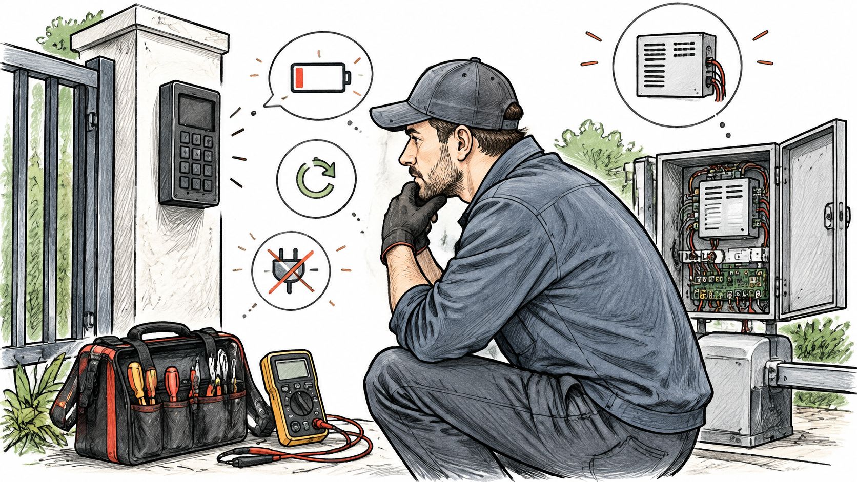
A dark or rebooting pad should be treated as a supply problem first. The test that matters is voltage at the keypad while the pad is lit or trying to transmit. A reading at the transformer alone can't clear the cable, splices, or terminals between the source and the pad.
Run the Checks in Order
Isolate power before touching terminals. Switch off operator power before loosening any terminal, and don't work on a live mains transformer. Low voltage keypad wiring still sits near equipment that can start a motor.
Inspect the path before using a meter. Look at the transformer, fuses, terminal screws, splices, and cable jacket for corrosion, green or white buildup, a chewed cable, cracked insulation, or a splice sitting in water. Pull gently on a lug only with power off, since a wire that moves under a screw can pass voltage one minute and fail the next.
Measure under load at the pad. Restore power and measure at the keypad terminals while the pad is illuminated or transmitting, not with the wires lifted. A weak transformer or high resistance splice can show a normal reading with no load and collapse when the pad draws current.
Compare the reading with that model's manual. One manufacturer keypad manual specifies 10 to 16.5 volts AC or 12 to 24 volts DC, recommends a transformer rated at least 16.5 VAC and 20 VA, and warns that power wiring runs longer than 200 feet can create problems when the wire is too small for the distance. Those figures belong to that manual, so a different brand must be judged by its own stated range.
Measure at the source and at the pad. Low voltage only at the pad points to distance, thin conductors, a loose lug, corrosion, or a wet splice. Low voltage at both ends points to the transformer, battery, fuse, or operator accessory output.
Don't borrow a nearby terminal. A spare looking low voltage terminal may be the wrong type, polarity, or current capacity. Confirm AC or DC, polarity, voltage range, and current from both manuals before any substitution, and stop if either manual is missing.
Record and restore exactly. Write down the source reading, the keypad reading, and whether the pad was lit during the test. Restore polarity exactly as found, keep power wires separate from relay contacts, and tighten terminals with power off.
A pretty voltage reading with the wires disconnected proves very little. The pad has to hold voltage while it's drawing current.
Read the Result
| Reading at the keypad | What it points to | Next step |
|---|---|---|
| Below the range in the model's manual | Weak supply, long or thin run, loose lug, or wet splice | Check the source and wiring, then retest under load |
| In range at source, low at keypad | Distance, conductor size, or a bad connection | Inspect splices and terminals before replacing anything |
| Low at both source and keypad | Transformer, battery, fuse, or accessory output | Check the supply device against its rating |
| In range but pad still dead or resetting | Keypad board, cable damage, or an intermittent connection | Record both readings and move to the code check in the next section |
| Above the overvoltage limit in the model's manual | Supply mismatch | Correct the supply before any further test |
A pad that lights, then reboots when a key is pressed, fits voltage sag. The press adds load, the supply drops, and the pad restarts before it can send a command. Replacing that pad without fixing the run usually produces the same reboot.
Distance deserves respect on gated entries. The keypad may sit far from the operator, with splices in a pedestal, a junction box, or conduit that collects water. Conductor size and run length must match the manual, because resistance in a long thin pair steals voltage before it reaches the pad.
Stop when readings don't match the wiring diagram, when line voltage work is required, or when the model manual is missing. Don't guess what a lamp pattern means. Give the technician the two readings, the model numbers, and a photo of the terminal labels taken with power off.
Follow the Code From Pad to Operator
Assume the face is lit and loaded voltage matches the manual. The remaining question is where the command stops. Splitting that path into stages keeps a manager from buying another keypad for a fault in a relay, an operator input, or a photo eye.
Think of the command as a handoff. The pad accepts a credential, the output changes state, the operator receives that change, and safety inputs allow movement. A failure at any handoff leaves the gate still.
Stage One and Two
1. Prove code acceptance. Enter a code known to be valid and watch for the acceptance beep, LED, display message, or relay click the keypad manual describes. Don't invent a meaning for a blink pattern that the manual doesn't define.
No acceptance calls for a programming check, not a parts order. Confirm the admin code, check for a lockout after wrong tries, look for a time schedule, confirm relay pulse length, and verify that the user still has permission. A delivery code that expired by schedule can look like a dead pad to the driver.
2. Prove the output changes state. A qualified person can meter the relay COM and NO terminals during the programmed pulse, as described in the replacement access control keypad checklist, which separates command generation, relay transfer, operator input, and safety interlock stages. Many standalone pads use a momentary dry contact, but the operator manual decides whether its open input expects COM to NO, a normally closed circuit, a maintained signal, or a proprietary data connection.
That manual check matters during replacement. A pad can click correctly and still be wired to the wrong input type. Anyone comparing an added controller should start with wiring help for smartphone gate access and the operator diagram, rather than matching wire colors from the old unit.
Stage Three and Four
3. Test the operator side. If the relay changes state and the gate doesn't move, try the same open command from a remote or from the controller input the manual identifies. Then inspect photo eyes, safety edges, emergency stop circuits, loop detectors, and obstruction memory. A functioning keypad can't override a safety lockout.
A remote that also fails strengthens the operator side finding. A remote that works while the relay pulse is present points to the wire pair or input terminal between the pad and the controller. Either result is more useful than another PIN change.
4. Condemn the pad last. If voltage is stable as the model's manual requires, a known valid code is accepted, lockouts and schedules are clear, and the relay never changes state, the pad or its output is the likely part. Until those points are proved, hardware failure is a guess.
Don't short operator terminals as a test unless the manufacturer explicitly permits that exact pair. The wrong pair can damage control electronics or defeat a safety control.
Prove the Repair
After a repair, run repeated successful cycles before returning the entry to normal use. A practical test set includes code acceptance, relay pulse, full gate travel, obstacle reversal by the method the operator manual allows, and recovery after power is removed and restored. Present that cycle count as a service recommendation, then follow any stricter test the manufacturer requires.
Write down the loaded voltage, whether the code was accepted, relay timing, and sensor status. Add the date, weather, and which other controls worked. That note turns the next electric gate keypad not working call into a comparison, instead of a fresh guess at the pedestal.
Rain, Heat, and Outages That Mimic a Bad Pad
After overnight rain, the keypad accepts a PIN but the gate stays still. That can point to moisture at a cable entry, while a dark keypad may indicate lost power. Weather can also trigger a safety lockout, so check what changed before condemning the pad.
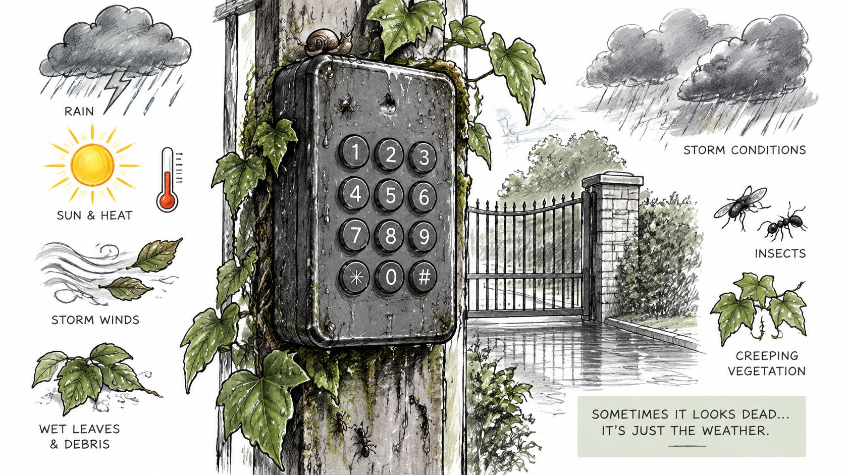
Keep a brief weather log: note the time, conditions, whether remotes failed too, and whether the keypad recovered on its own. Look for condensation behind the faceplate, a damaged seal, an open conduit entry, corrosion on terminals, or ice on the buttons. If the keypad is dark, have a qualified technician check its power supply rather than opening energized equipment yourself.
An exterior keypad specification lists an IP55 rating, an operating range of -31°F to 150°F (-35°C to 66°C), and operation at up to 95% relative humidity when installation guidelines are followed. IP55 covers dust and water jets, not submersion or water trapped inside cable entries. These limits apply to that model; check the rating for the keypad installed at your gate.
Drying the housing is a temporary test, not a repair. If the pad works after drying but fails in the next rain, inspect the gasket, drainage, conduit opening, and splice location. Correct the path that lets water in before replacing the keypad, or the new part may face the same fault.
Power outages create a different pattern. Note whether the keypad returns when power is restored, reboots when a button is pressed, or loses power as the motor starts. A battery may show an acceptable reading at rest yet drop under motor load; have a qualified technician test the battery and charging system under load.
Network-dependent access can also fail during a storm if the local connection goes down. A cellular-based option such as Nimbio does not require Wi-Fi at the gate; see this Wi-Fi vs LTE gate security comparison. Also check that the keypad is rated for its outdoor location. A matching cutout does not make an indoor-rated pad suitable for installation outside.
Keep Shared Codes Out of the Repair
A dead pad creates pressure to post one shared code on a sign or text it to every resident. That fixes the queue for an afternoon and creates a credential problem that lasts much longer. A shared code can't show which driver entered, and it can't be revoked for one person without changing access for everyone.
Predictable codes add a second weakness. People choose repeated digits and obvious sequences, and anyone trying common patterns first benefits from those habits. A longer code helps only when it isn't shared, reused, watched during entry, or written where drivers can see it.
A Tighter Outage Routine
- List who needs entry: Name the residents, staff, or vendors who must pass during the outage, rather than sending a code to the whole property.
- Limit any temporary code: Set it in the admin menu only, give it to the person who needs it, and keep it off signs, group texts, and the gate pedestal.
- Close the repair cleanly: Remove the temporary code after testing, change the admin code if it was shared, and store the new admin code with property records.
Where an access system supports individual digital keys with an end date, that path is cleaner than a communal number. The key can expire or be revoked for one holder. The pad can then be repaired without teaching every driver a code that nobody remembers to delete.
Repair the Pad or Call for the Operator
Repair or replace the keypad only when the evidence stays at the pad. Loaded voltage matches that model's manual, the housing is dry and sealed, a known valid code produces no relay change, and a remote still runs the gate. Those four points justify condemning the pad or its output.
Call a qualified gate or low voltage technician when the fault involves the operator board, a safety input, line voltage, a battery that fails under motor load, or wiring that can't be matched to the diagram. Local rules vary, so a community shouldn't remove a call box or change visitor access until someone has checked what its jurisdiction requires. Guidance on what to look for in a gate access system helps frame that decision before parts are ordered.
While parts are pending, use one planned parallel path rather than a posted shared code. Nimbio is one example of a cellular add-on controller that connects over LTE, so it needs no Wi-Fi at the gate, wires into the operator the property already has, and lets existing clickers, fobs, and keypads keep working alongside the app. Managers can issue and revoke digital keys remotely, set an expiration date, and let a visitor in remotely with video verification.
Physical installation is completed by independent professional gate technicians or local low voltage installers, and Nimbio recommends a licensed professional gate or low voltage technician. Nimbio can put customers in touch with an installer who has worked with Nimbio before on request, and its support team will confirm wiring compatibility before installation at 1-800-353-3422 if a customer is unsure about a gate model. Match one symptom, write down the two voltage readings, and give that note to the technician rather than forcing the gate.
When an electric gate keypad not working leaves a property dependent on a shared code, Nimbio adds cellular smartphone access through a controller that wires into the existing operator, needs no Wi-Fi at the gate, and leaves clickers, fobs, and keypads working. Property managers can issue, revoke, and set expiration dates on digital keys, and visitors can be verified by video and let in remotely.